Various Components Used In The UHF & Microwave Frequency Range
 |
KLYSTRON POWER SUPPLY |
 |
| KLYSTRON MOUNT |
 |
| DETECTOR MOUNT |
 |
| FIXED ATTENUATOR |
 |
| VARIABLE ATTENUATOR |
 |
| ROTARY VANE TYPE ATTENUATOR |
 |
| WAVE GUIDE STAND |
 |
| E-PLANE TEE (Please note the orientation) |
 |
| H-PLANE TEE (Please note the orientation) |
 |
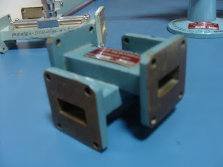
| MAGIC TEE |
 |
| E-PLANE BEND |
 |
| H-PLANE BEND |
 |
| E-H TUNER |
 |
| PRECISION SLIDE SCREW TUNER |
 |
| SLOTTED LINE SECTION WITH TUNABLE PROBE |
 |
| DIRECT READING FREQUENCY METER |
 |
| MATCHED TERMINATION |
 |
| MOVABLE SHORT |
 |
| T-CIRCULATOR |
 |
| CROSS DIRECTIONAL COUPLER |
 |
| MULTI-HOLE DIRECTIONAL COUPLER |
 |
| PICK-UP HORN ANTENNA |
 |
| GUNN POWER SUPPLY |
 |
| GUNN OSCILLATOR |
 |
| PIN MODULATOR |
Some Basic Questions -
1. How to find the least count of Slotted Line Section?
The slotted line section of a main scale is graduated in centimeters and millimeters. On the vernier scale of the Slotted Line Section, 0.9 cm is divided into ten equal parts. The least count of the Slotted Line Section can be calculated as follows:
Least count = one main scale (MS) division - one vernier scale (VS) division.
= 1 mm – 0.09 mm = 0.1 mm = 0.01 cm
List of Experiments -
1.A. To study various components used at UHF & Microwave Range.
B. To study the basic set up for the generation of Microwave Power.
2. To study the characteristics of Reflex Klystron and to determine its Electronic Tuning Range.
3. To demonstrate the relationship between frequency, wavelength in free space and guide wavelength.
4. To study various Microwave Tees i.e. E – plane Tee, H – plane tee & E-H plane Tee.
5. To measure Large Voltage Standing Wave Ratio.
6.A. To plot the radiation pattern of Pyramidal Horn Antenna.
B. To determine the gain of Pyramidal horn Antenna.
7. To measure Coupling and Directivity of directional coupler.
8. To study the V-I characteristics of Gunn diode.
9. To study Microstrip Technology & Advanced Microstrip Trainer kit.
*****************************************************************************
Experiment 1.B. (Contributed by Amrita Singh, Mayank Moghe and Pratik Patil)
Aim: To study basic setup for generation of microwave power.
• Beam Voltage –
• Beam Current –
• Repeller Voltage –
• Repeller Current –
• Operating Frequency –
Procedure:
1. Arrange the setup as shown in the fig.
2. Start the cooling fan first.
3. Keep the knob at CW position.
4. Beam voltage knob at minimum position.
5. Repeller voltage knob at clockwise minimum position.
6. Variable attenuator at maximum attenuation position.
7. Frequency meter at minimum position.
8. Slotted line section at minimum position.
9. Now start KPS and move the knob to V position and vary the beam voltage which should not exceed 300V.
10. Now move the knob to current position and measure the corresponding beam current which should not be more than __mA.
11. Now move the knob to OFF position first and then move it to REP position to measure the repeller voltage.
12. Now start observing the milliammeter and note down the maximum current reading. If it isn’t showing deflection then start minimizing attenuation & vary the repeller voltage till the current becomes maximum. This is beam current.
13. Now start varying the frequency meter till __ power gets absorbed.
14. At some particular frequency it will show a dip on the milliammeter. This is the operating frequency.
Readings:
• Beam Voltage –
• Beam Current –
• Repeller Voltage –
• Repeller Current –
• Output Frequency –
********************************************************************************
Experiment 4. (Contributed by Amrita Singh, Mayank Moghe and Pratik Patil)
Aim: To study the various waveguide Tees. E plane Tee, H plane Tee and E-H plane Tee.Procedure:
1) Arrange the apparatus as shown in the figure.
2) Tune the as shown in figure.
3) Measure Beam Voltage, Beam Current, Repeller Voltage and maximum output current.
4) Now remove the mA and connect the voltmeter and measure the power in terms of voltmeter. (1.2V)
5) Now remove detector mount and connect H plane Tee with its side arm, i.e., port 3.
6) Terminate port 2 and measure power at port 1 that will be 0.6V.
7) Reverse the connection and measure power at port 2.
8) This is used to detect only the magnitude. Phase is not detected here because phase detector is not available.
9) Repeat the procedure for E plane Tee.
10) In case of Magic Tee, connect port 3 to main waveguide and measure power at port 1 with port 2 and port 4 terminated.
11) Similarly connect port 4 and observe power at port 1 with port 2 terminated. Power at port 3 will be zero.
********************************************************************************
Experiment 8. (Contributed by Amrita Singh, Mayank Moghe and Pratik Patil)
Aim: To study the V-I characteristics of Gunn Diode.
Theory: The Gunn oscillator is based on negative differential conductivity effect in bulk ___ semiconductor which has two conductors___ minima separated by an energy gap. A practical Gunn diode consists of a slice with a buffer layer in between the active layer and substrate.
Gunn Effect: Above some critical voltage corresponding to an electric field of 2000-4000 volts/cm, the current in every specimen became a fluctuating function of time.
In GaAs specimens, this fluctuation took the form of a periodic oscillation superimposed upon the pulse current...The frequency of oscillation was usually determined mainly by the specimen, and not by the external circuit.
Works on transferred electron mechanisms
It is used in low power microwave oscillators
-->Radar transmitter
-->Combinational & Sequential logic circuits
-->Broad band linear amplifier
**********************************************************************************
Assignment 1.A.
1. How are the Microwave Components classified?
2. In which frequency band is the set up arranged?
3. State True or False -
a. Gunn diode works as an oscillator when operated in the negative differential region.
b. E-plane Tee acts as an adder & H-plane Tee acts as a subtractor.
Assignment 1.B.
Distinguish between 2 cavity & Reflex Klystron by stating at least 10 points.
Assignment 2.
1. With the help of Applegate Diagram explain velocity modulation and bunching process in reflex klystron in brief.
2. What are the applications of Reflex Klystron.
Assignment 3.
1. State the difference between circulator and coupler.
2. What are ferrites? Why are they useful in microwaves?
Assignment 4.
1. What is the role of tees in microwave set up?
2. Explain magic tee and write a scattering matrix for it.
Assignment 5.
1. Why VSWR cannot be infinite?
2. What is matched termination?
Assignment 6.A.
1. What is primary and secondary antenna?
2. What is Radiation Pattern?
Assignment 6.B.
Give an example of each of the following antennas -
Wire Antennas
Microstrip Antennas
Reflector Antennas
Travelling Wave Antennas
Aperture Antennas
Assignment 7.
1. State whether directional coupler is reciprocal or non- reciprocal device?
2. How a 4-port coupler can be used as a 3-port coupler?
Assignment 8.
1. Explain the Gunn Effect.
2. Explain various application of the Gunn diode.
Grading -
The practical journal should be completed neatly with one page left blank between the two experiments. Margins should be drawn wherever required. Graphs & observation table should be drawn very nicely. Discussion questions should be brief and concise (The length wouldn't count but whatever has been written should make sense!!!!!!).
A student adhering to all the above mentioned points will be getting the maximum marks. Keeping these students as reference, I will grade all the other students. This is because I want to duly award those who have put in a lot of efforts.
But I will also give a due credit to all of them, if I find that the students are improving for good!!!!!!!
BATCH -2011-12
Important Deadlines for submission of practicals-
AUGUST 20th 2011 - Batches E1, E2 and E3
Internal Viva- AUGUST 20th 2011 - Batches E1, E2 and E3
AUGUST 22nd 2011- Batch E2
AUGUST 24th 2011- Batch E3
AUGUST 26th 2011- Batch E1
ANSWER THE FOLLOWING QUESTIONS FROM UNIT 6 ONLY AND SUBMIT IT BY 18TH AUGUST 2011 ALONG WITH CAT 2. FORM OF SUBMISSION - SEPARATE SHEETS OF LOOSE PAPER STAPLED TOGETHER.
ASSIGNMENT QUESTIONS -
1. What is Gunn Effect? Draw energy band diagram of GaAs diode and explain the principle of operation.
2. Describe the various modes of operation for Gunn diode.
3. What is a PIN diode? Describe the construction of a PIN diode and its characteristics.
4. Write a short note on characteristic impedance of microstrip lines.
NOT APPLICABLE-
BATCH -2010-11
Important Deadlines for submission of practicals-
AUGUST 23rd 2010- Batch E2
AUGUST 25th 2010- Batch E3
AUGUST 27th 2010- Batch E1
AUGUST 30th - SEPTEMBER 4th
Tentative Schedule (Obviously subject to change)-SEPTEMBER 1st - Batch E3
SEPTEMBER 3rd - Batch E1
BEST OF LUCK!!!!!!!!!!!!!!!!!!!!!!!!!!!!!!!!!!!!!!!!!!!!!!!!!
Wave guide and Magic tee
ReplyDelete